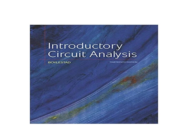
Introductory circuit analysis 13th ed – Introductory Circuit Analysis, 13th Edition, provides a comprehensive and engaging introduction to the fundamentals of electrical engineering. Written by renowned author Robert Boylestad, this textbook has been trusted by generations of students and professionals for its clear explanations, in-depth coverage, and practical applications.
The 13th edition has been thoroughly updated to reflect the latest advancements in the field, including new content on renewable energy sources, power electronics, and computer-aided design (CAD) tools. It also features a wealth of new examples, exercises, and design problems to help students master the concepts and skills essential for success in electrical engineering.
1. Introduction to Introductory Circuit Analysis

Introductory circuit analysis is the study of the behavior of electrical circuits, which are networks of interconnected components that allow the flow of electric current. It forms the foundation for understanding more advanced topics in electrical engineering, such as power systems, electronics, and communication systems.
The 13th edition of Introductory Circuit Analysis is designed for undergraduate students in electrical engineering and related fields. It assumes a basic understanding of physics, including concepts such as force, energy, and power. No prior knowledge of circuit analysis is required.
The textbook is organized into six chapters, each covering a specific aspect of circuit analysis. Chapter 1 provides an introduction to the subject and its applications. Chapter 2 covers the basic concepts of voltage, current, resistance, and power. Chapter 3 discusses DC circuits, including series and parallel circuits, voltage and current distribution, and mesh and nodal analysis.
Chapter 4 introduces AC circuits, including sinusoidal waveforms, impedance, reactance, and resonance. Chapter 5 covers circuit analysis techniques, including the Laplace transform, Fourier series, and computer-aided design (CAD) tools. Chapter 6 discusses the applications of introductory circuit analysis in various fields of engineering.
2. Basic Concepts and Circuit Elements
The fundamental concepts of circuit analysis are voltage, current, resistance, and power. Voltage is the difference in electrical potential between two points in a circuit, and it is measured in volts (V). Current is the flow of electric charge through a circuit, and it is measured in amperes (A).
Resistance is the opposition to the flow of current in a circuit, and it is measured in ohms (Ω). Power is the rate at which electrical energy is transferred or consumed in a circuit, and it is measured in watts (W).
Circuit elements are devices that can store or dissipate electrical energy. The three basic types of circuit elements are resistors, capacitors, and inductors.
- Resistors oppose the flow of current and dissipate electrical energy as heat.
- Capacitors store electrical energy in an electric field.
- Inductors store electrical energy in a magnetic field.
Simple circuits can be analyzed using Ohm’s law and Kirchhoff’s laws.
- Ohm’s law states that the voltage across a resistor is directly proportional to the current flowing through it.
- Kirchhoff’s current law (KCL) states that the sum of the currents entering a node in a circuit is equal to the sum of the currents leaving the node.
- Kirchhoff’s voltage law (KVL) states that the sum of the voltages around a closed loop in a circuit is equal to zero.
3. DC Circuits
DC circuits are circuits that contain only DC sources, such as batteries and power supplies. DC sources provide a constant voltage or current, and they do not change polarity over time.
Series circuits are circuits in which the components are connected in a single loop. In a series circuit, the current is the same throughout the circuit, and the voltage across each component is equal to the voltage of the source.
Parallel circuits are circuits in which the components are connected in multiple loops. In a parallel circuit, the voltage is the same across each component, and the current is divided among the components.
DC circuits can be analyzed using mesh and nodal analysis.
- Mesh analysis is a method for analyzing circuits that contain multiple loops.
- Nodal analysis is a method for analyzing circuits that contain multiple nodes.
4. AC Circuits

AC circuits are circuits that contain AC sources, such as generators and transformers. AC sources provide a voltage or current that varies sinusoidally over time.
Sinusoidal waveforms are characterized by their amplitude, frequency, and phase.
- The amplitude is the maximum value of the waveform.
- The frequency is the number of cycles per second.
- The phase is the angle between the waveform and a reference point.
Impedance is the opposition to the flow of AC current in a circuit. Impedance is measured in ohms (Ω), and it is a complex quantity that has both a magnitude and a phase angle.
Reactance is the imaginary part of impedance. Reactance is measured in ohms (Ω), and it can be either positive (inductive) or negative (capacitive).
Resonance occurs when the inductive reactance and capacitive reactance in a circuit cancel each other out. At resonance, the impedance of the circuit is at a minimum, and the current is at a maximum.
5. Circuit Analysis Techniques: Introductory Circuit Analysis 13th Ed

The Laplace transform is a mathematical tool that can be used to analyze circuits in the frequency domain. The Laplace transform converts a time-domain signal into a frequency-domain signal.
Fourier series is a mathematical tool that can be used to represent periodic waveforms as a sum of sinusoidal waveforms. Fourier series can be used to analyze circuits that contain periodic waveforms.
Computer-aided design (CAD) tools can be used to simulate and analyze circuits. CAD tools can help engineers to design and troubleshoot circuits more efficiently.
6. Applications of Introductory Circuit Analysis
Introductory circuit analysis is used in a wide variety of fields of engineering, including:
- Power systems
- Electronics
- Communication systems
- Control systems
- Signal processing
Introductory circuit analysis is essential for understanding the behavior of electrical circuits and for designing and troubleshooting electrical systems.
Common Queries
What is introductory circuit analysis?
Introductory circuit analysis is the study of the basic concepts and principles of electrical circuits. It covers topics such as voltage, current, resistance, power, and circuit analysis techniques.
Who is the target audience for Introductory Circuit Analysis, 13th Edition?
Introductory Circuit Analysis, 13th Edition, is intended for undergraduate students in electrical engineering and related fields. It is also a valuable resource for professionals who need to refresh their knowledge of the fundamentals of electrical engineering.
What are the prerequisites for Introductory Circuit Analysis, 13th Edition?
The prerequisites for Introductory Circuit Analysis, 13th Edition, are a basic understanding of algebra and trigonometry.
